

From Single Point of Failure to Warm Standby: A Practical Core Switch Disaster Recovery Playbook
Overview
Every organization depends on its network to keep operations running. But for us, the stakes were higher than most. Our core business operations, internal systems, communications and cross-team workflows run entirely on this network. On top of that, our Customer Service team operates 24/7. Every minute of downtime means users go unhandled, tickets pile up, and response-time commitments are at risk.
The risk was hiding in plain sight: a single networking device with no backup. In infrastructure terms, this is called a Single Point of Failure, one device whose failure brings down the entire system with it. No redundancy, no fallback, no safety net.
This post is about how we identified that risk and built a practical backup plan for our core network one that can restore connectivity in under 30 minutes when the main device fails. We'll walk through what the problem was, what we built, how it works, and what we learned along the way.
No matter your background whether you manage budgets, run operations, or configure switches this post is written for you.
Problem Statement
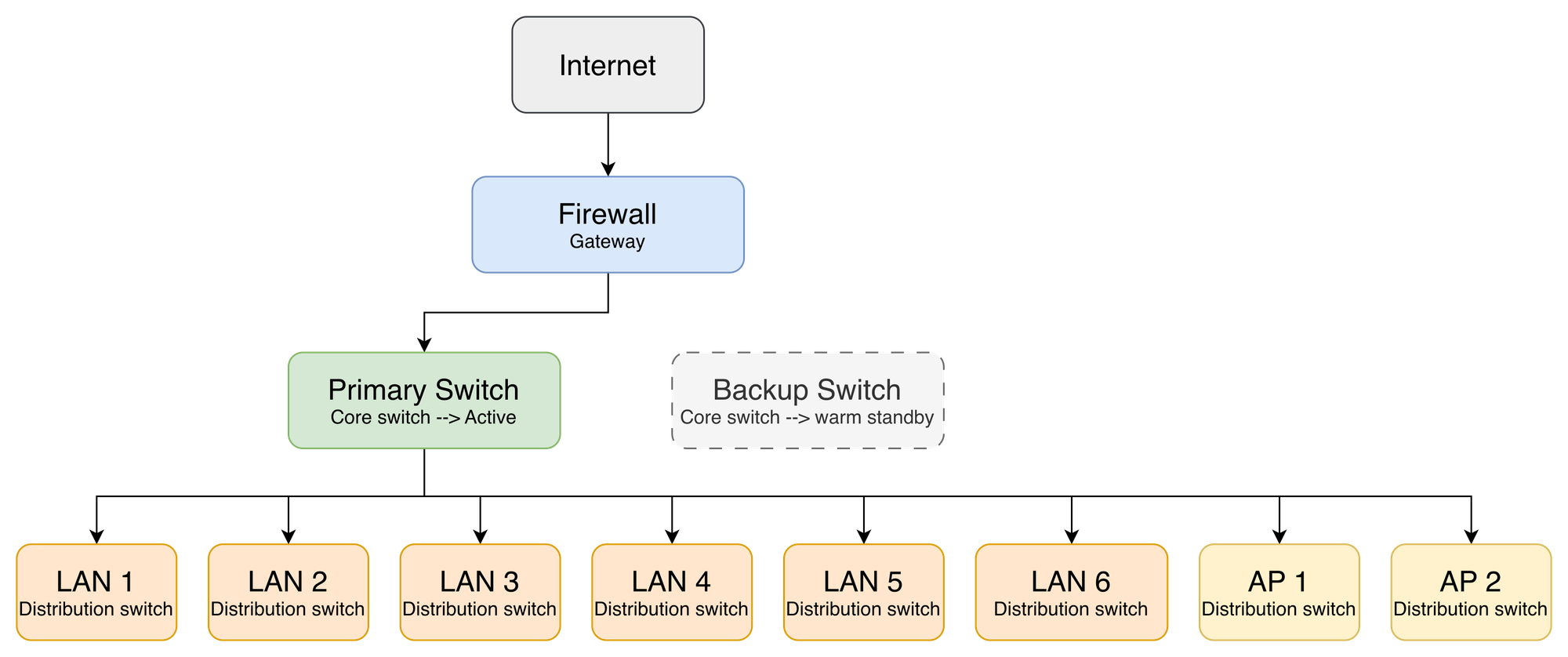
Our network topology centered on a Fortigate Firewall as the gateway, connected to a single core switch that distributed connectivity to all distribution switches and access points across the building. Every part of the business depended on this one device which made it a Single Point of Failure.
The entire organization relies on this network around the clock. Business operations run on it continuously approvals, coordination, internal tooling, and cross-team workflows all depend on it being available. Our Customer Service team operates 24/7, directly serving users in real time. When the network is up, all of this runs seamlessly.
But with a single core switch, that reliance depended entirely on one device staying healthy. A hardware failure, power issue, or unresponsive device would interrupt every network segment and every connected user at once. For business operations, that meant work coming to a halt. For Customer Service, it meant being unable to serve users and breaching response-time commitments.
The more critical the network became to daily operations, the more important it was to ensure it could recover quickly from any failure. We needed a fallback that was fast to activate and dependable to execute.
What We Implemented
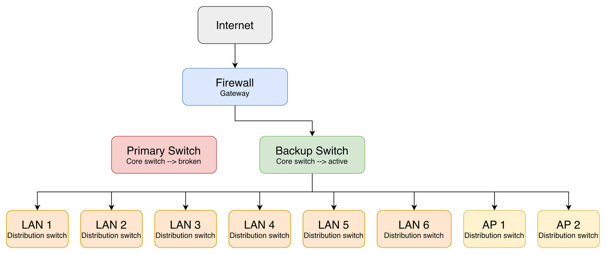
The solution we chose was Warm Standby. We keep a second switch one we already owned sitting on standby: powered on, fully configured, but not actively handling any traffic. Because the hardware was already in our inventory, this added no extra cost. If the main switch fails, the team physically moves the cables over to the backup switch and the network comes back up.
We chose Warm Standby over full active-active redundancy deliberately. Identical hardware pairs with automatic failover protocols add significant cost and operational complexity that wasn't justified at our scale. Warm Standby gives us a dependable recovery path at a fraction of that investment. The backup switch stays powered on and fully configured at all times ports are either administratively down or cables simply aren't connected to the production path, keeping it logically isolated until the moment it's needed.
Before deciding on the approach, we aligned with both business operations and the Customer Service team to define the acceptable recovery window. The agreement: full network recovery should take no longer than 30 minutes. That number became the target the design had to meet.
For both business operations and Customer Service, the switchover process itself is the recovery. Moving the cables to the backup switch restores the full network within the agreed 30-minute window.
For Customer Service specifically operating 24/7 and serving users in real time, we added an extra safeguard so they aren't left waiting during a switchover. A backup Wi-Fi network stays active at all times, completely independent of the core switch. The moment the main network goes down, the Customer Service team can connect to this backup Wi-Fi and continue serving users while the full recovery is underway.
How the System Works
On normal days, everything runs through the main switch as usual. Traffic flows invisibly from the internet through the Fortigate firewall, into the primary core switch, and out to every LAN segment and access point across the building. Nobody notices the backup switch sitting in warm standby it's powered on, fully configured, and waiting.
When something goes wrong, the Fortigate fires an alert for Port 9 DOWN, or the primary switch becomes completely unresponsive. At that point the procedure is physical and deliberate two steps executed in sequence.
Step 1 — Uplink swap: Disconnect the cable from Fortigate Port 9. Plug in the pre-positioned standby cable running from the backup switch uplink port. This cable has been pre-routed and labeled "IDLE" in the rack since day one, no searching, no improvising under pressure. The moment it's connected, the backup switch has an uplink to the internet.
Step 2 — Downlink migration: Move all 8 distribution cables from the primary switch to their pre-mapped ports on the backup switch. Every cable is labeled at both ends. The port mapping is documented, printed, and physically available inside the server room. The whole process completes within the agreed 30-minute recovery window.
While the switchover is underway, the Customer Service team isn't left waiting. They switch over to the backup Wi-Fi network always active and independent of the core switch and continue serving users while the full recovery is in progress.
Technical Implementation
The key principle here is simple: the standby switch must be an exact mirror of the primary at all times. Not just when it's first set up every configuration change on the primary needs to be replicated to the standby immediately. The moment they drift, the failover becomes unpredictable.
Below are the main areas of configuration, each with an illustrative example. Actual values IPs, VLAN IDs, interface numbers differ per environment.
VLAN parity
The standby switch must have an identical VLAN database to the primary. This is the most critical part a VLAN that exists on the primary but not the standby means that segment goes dark after failover, even if everything else works.
! Create matching VLANs on standby switch
vlan 10 20 30 100 200
 name vlan 10 USER-LAN
 name vlan 20 VOICE
 name vlan 30 GUEST
 name vlan 100 MGMT
 name vlan 200 SERVERS
Port configuration
There are two types of ports to configure the uplink facing the firewall, and the downlinks facing each distribution switch. Both carry tagged traffic for all VLANs.
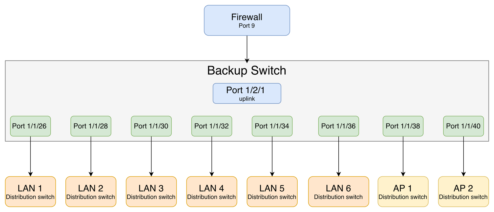
Uplink — firewall-facing: Pre-configured and waiting. The moment the standby cable goes into Fortigate Port 9, this link is live.
! Uplink to Fortigate firewall
interface ethernet 1/2/1
 port-name UPLINK-FW
 tagged vlan 10 20 30 100 200
 no shutdown
Downlinks — distribution-facing: Each port maps to one downstream device. Port names match the cable labels — no guesswork during failover.
! Example: downlink trunk to a distribution switch
interface ethernet 1/1/26
 port-name LAN-1
 tagged vlan 10 20 30 100 200
 no shutdown

interface ethernet 1/1/28
 port-name LAN-2
 tagged vlan 10 20 30 100 200
 no shutdown

! ... repeat for each downstream port up to 1/1/40
Customer Service backup Wi-Fi
This is configured completely independently of the core switch. The Mikrotik acts as a standalone gateway for the Customer Service backup Wi-Fi. Its own DHCP pool, its own default route upstream. It has no dependency on the core switch, which is exactly the point.
! Dedicated IP pool for Customer Service backup segment
/ip pool
add name=cs-backup ranges=192.168.x.10-192.168.x.254

! DHCP server on the backup interface
/ip dhcp-server
add interface=etherX address-pool=cs-backup disabled=no

/ip dhcp-server network
add address=192.168.x.0/24 gateway=192.168.x.1

! Default route to upstream ISP or secondary link
/ip route
add dst-address=0.0.0.0/0 gateway=<upstream-gw>
Unlike the core switch failover, this path requires no intervention during an incident. The backup Wi-Fi stays active at all times the moment the main network goes down, the Customer Service team connects to it and continues serving users while the full recovery is underway.
Post-failover validation:
| Test | Expected result |
|---|---|
| Ping gateway + 8.8.8.8 | Reachable |
| DHCP lease check per LAN segment | IPs assigned on all segments |
| SSID broadcast from both APs | Visible and connectable |
| Customer Service backup Wi-Fi | Active and serving users |
Result and Impact
Before relying on this setup during a real incident, we ran a full controlled simulation deliberately triggering the failover procedure during a planned maintenance window to verify that everything actually worked
| Metric | Target | Result |
|---|---|---|
| Full failover time | < 30 minutes | On target |
| Customer Service availability | Stay operational during failover | Maintained via backup Wi-Fi |
| VLAN configuration issues | None | Zero (Parity validated pre-incident) |
| Rollback time if needed | < 30 minutes | Confirmed via reverse procedure |
Conclusion
The investment here was modest a standby switch we already owned, some preparation work, one planned simulation. What we got in return: confidence that if the main network device fails, we have a clear, practiced, documented recovery path. Business operations are restored within the agreed 30 minute window, and Customer Service stays operational throughout via the always-on backup Wi-Fi.
This reduces our exposure to a single point of failure, for a relatively small upfront effort. And unlike many IT projects, the outcome of this one is visible to everyone the moment the main switch fails the network keeps running.
Warm Standby matched our scale and constraints, with low cost and operational overhead. Three things made the difference:
Config parity is a living requirement. Keeping every VLAN and routing change on the primary replicated to the standby is what makes the failover dependable when it matters most.
Physical pre-positioning pays off. A pre-labeled cable already routed to the right rack turns a high-pressure moment into a simple, repeatable action. The preparation is the resilience.
Simulate before you need it. Practicing the failover during a planned window gave us confidence the plan works, and surfaced small refinements while they were still cheap to make.
Ultimately, leveraging existing infrastructure meant achieving this baseline resilience at zero additional hardware cost showing that this kind of resilience can come from operational discipline rather than significant spend.
If your network still relies on a single core switch with no fallback, this is a practical, low-complexity first step toward stronger resilience one you can build on as your needs grow.
About Halodoc
Halodoc is the number one all-around healthcare application in Indonesia. Our mission is to simplify and deliver quality healthcare across Indonesia, from Sabang to Merauke.
Since 2016, Halodoc has been improving health literacy in Indonesia by providing user-friendly healthcare communication, education, and information (KIE). In parallel, our ecosystem has expanded to offer a range of services that facilitate convenient access to healthcare, starting with Homecare by Halodoc as a preventive care feature that allows users to conduct health tests privately and securely from the comfort of their homes; My Insurance, which allows users to access the benefits of cashless outpatient services in a more seamless way; Chat with Doctor, which allows users to consult with over 20,000 licensed physicians via chat, video or voice call; and Health Store features that allow users to purchase medicines, supplements and various health products from our network of over 4,900 trusted partner pharmacies. To deliver holistic health solutions in a fully digital way, Halodoc offers Digital Clinic services including Haloskin, a trusted dermatology care platform guided by experienced dermatologists.
We are proud to be trusted by global and regional investors, including the Bill & Melinda Gates Foundation, Singtel, UOB Ventures, Allianz, GoJek, Astra, Temasek, and many more. With over USD 100 million raised to date, including our recent Series D, our team is committed to building the best personalized healthcare solutions — and we remain steadfast in our journey to simplify healthcare for all Indonesians.